 DataSheet
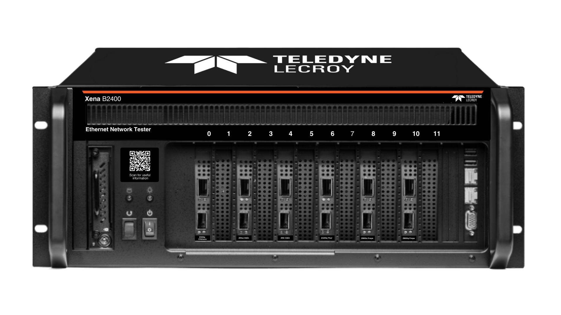
Award Winning Solutions
Xena has won multiple global awards for price/performance and technical innovation. Learn more.

Technical Expertise
Copyright © 2009-2024 Teledyne LeCroy Xena ApS, Denmark
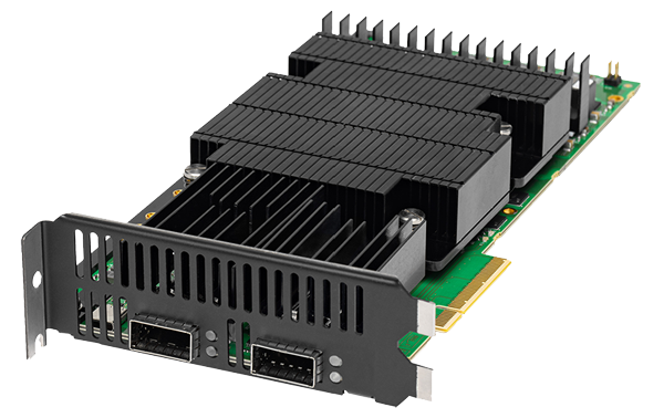
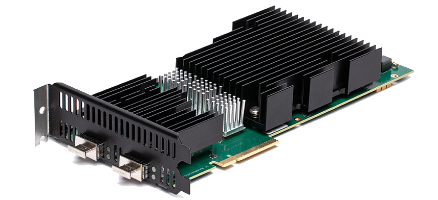
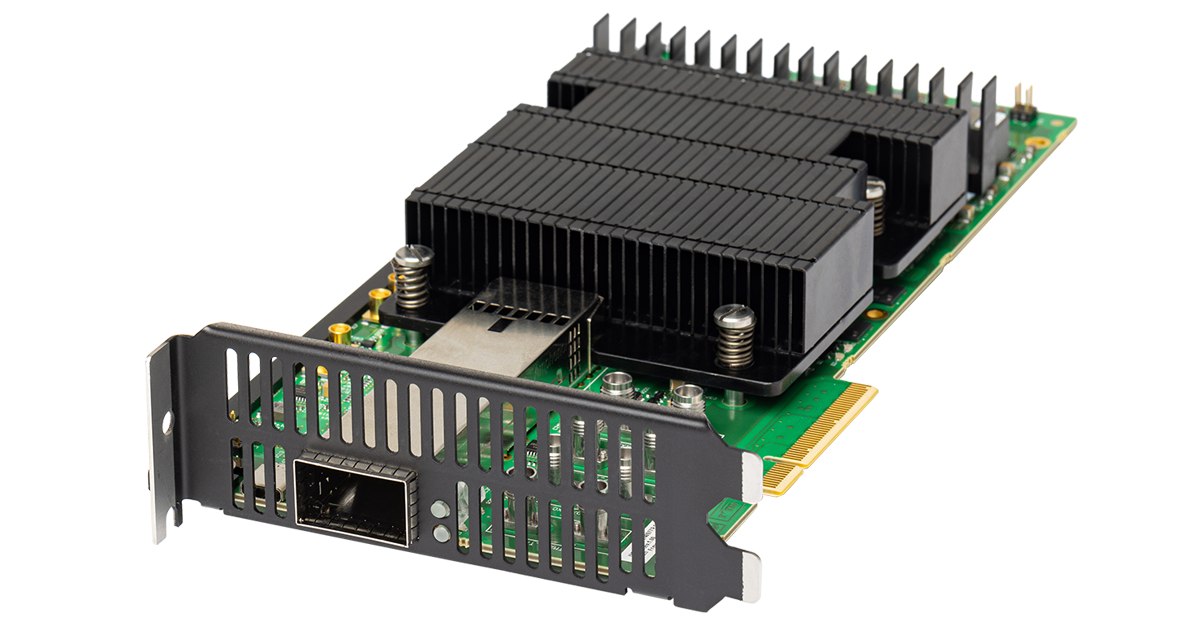
The Z800q Freya Ethernet traffic generator can test 800GE, 400GE, 200GE, 100GE and 50GE using 112G/56G SerDes PAM4
A versatile solution for performance and functional testing of Ethernet network infrastructure and equipment including switches, routers and NICs, the Z800q Freya can test up to 800GE using 112G SerDes (PAM4 112G) and is designed for helping achieve the best possible signal integrity and Bit Error Rate performance.
The Z800q offers extensive L1 test features for advanced PCS and PMA layer testing including dynamic transceiver clock sweep, lane skewing and PRBS modes. Signals can be analyzed in advanced signal integrity view, which provides visual information on the quality of the signal.
The Z800q Freya test module also supports Auto-Negotiation and Link Training (AN/LT) on 112G SerDes and 56G SerDes.
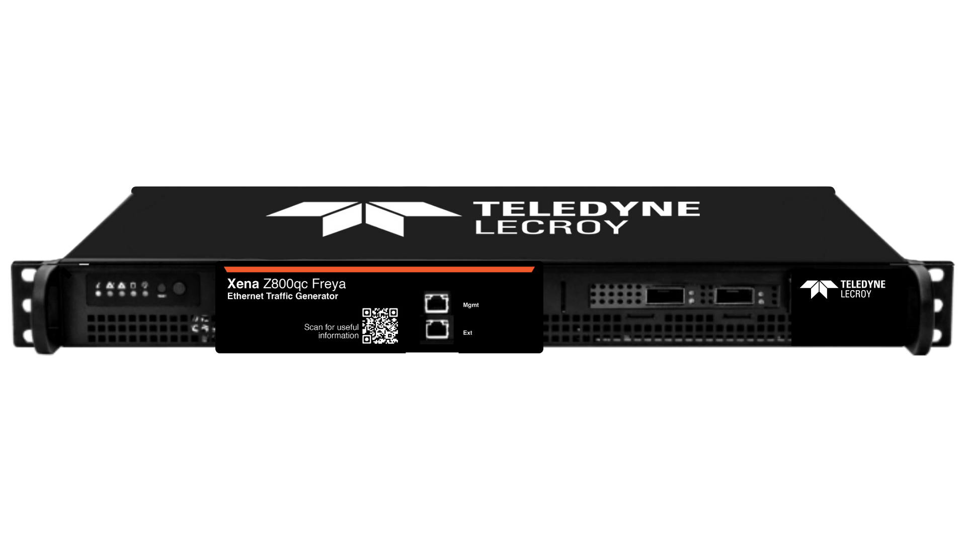
Z800q Freya modules can be installed in the modular XenaBay B2400 chassis, or in the fixed XenaCompact chassis, making it the most compact and lightweight 800G Ethernet test solution in the market.
XenaManager is included, giving users access to an intuitive user-friendly multi-user management software where they can generate and analyze traffic. Xena OpenAutomation (XOA) enables customers to make the most of Xena testers with tailored tests as well as standardized test methodologies, to achieve accelerated release cycles, enhanced test reliability, and boosted customer satisfaction.
Ethernet Auto-Negotiation & Link Training Test Tools
Freya customers can purchase Freya 800 AN/LT SW Lic license for enabling AN/LT Utility on Z800q Freya and Z800q Freya-OSFP modules. This license enables additional AN/LT tools for thorough testing of the endpoint behavior during the auto-negotiation and link training process.
The AN/LT Utility provides insight, visibility, and configuration possibilities to the AN and LT process making it easy to analyze DUT behavior during AN/LT, configure and optimize the relevant AN parameters and LT coefficients.
Top Features
QSFP-DD800 : 800G, 400G, 200G, 100G, 50G Ethernet
QSFP112 : 400G, 200G, 100G, 50G Ethernet
1x800G, 2x400G, 4x200G, 8x100G and 8x50G Ethernet
QSFP-DD800 cage:
112G SerDes:
1 x 800GE PAM4 802.3df (D2.0) / ETC* or
2 or 1 x 400GE PAM4 802.3ck or
4 or 2 x 200GE PAM4 802.3ck or
8 or 4 x 100GE PAM4 802.3ck
56G SerDes:
1 x 400GE PAM4 802.3bs or 802.3cd or
2 x 200GE PAM4 802.3cd or
4 x 100GE PAM4 802.3cd or
8 x 50GE PAM4 802.3cd
QSFP-DD112 cage:
112G SerDes:
1 x 400GE PAM4 802.3ck or
2 x 200GE PAM4 802.3ck or
4 x 100GE PAM4 802.3ck
56G SerDes:
1 x 400GE PAM4 802.3bs or 802.3cd or
2 x 200GE PAM4 802.3cd or
4 x 100GE PAM4 802.3cd or
8 x 50GE PAM4 802.3cd
Both cages must run with the same interface configuration (e.g. 4 x 100G) and same SerDes speed (e.g 112G)
Power capacity using single cage: QSFP-DD800: 25W or QSFP112: 15W
Power capacity using both cages: QSFP-DD800: 15W + QSFP112: 15W
**ETC = Ethernet Technology Consortium
Auto-negotiation: IEEE 802.3 Clause 73 and ETH. 400G/800G specifications
Link training: IEEE 802.3 Clause 136 and 161
RS-FEC (Reed-Solomon) (544,514,t=15), IEEE802.3 Clause 119
RS-FEC (Reed-Solomon) (544,514,t=15), IEEE802.3 Clause 134
RS-FEC (Reed-Solomon) (544,514,t=15), IEEE802.3 Clause 161 for 100GBASE
1 x QSFP-DD800 and 1 x QSFP112
Link state, FCS errors, pause frames, ARP/PING, error injections, training packet
All traffic: RX and TX Mbit/s, packets/s, packets, bytes
Traffic w/o test payload: RX and TX Mbit/s, packets/s, packets, bytes
Configurable from 16 to 56 bytes, default is 20B (12B IFG + 8B preamble)
Ability to adjust the effective line rate by forcing idle gaps equivalent to -1000 ppm (increments of 10 ppm)
From -400 to 400 ppm in steps of 1 ppm (shared across all ports)
Configurable linear or step sweep +/- 400 ppm
Supported (configurable IP and MAC address per port)
System is fully field upgradeable to product releases (FPGA images and software)
Enable/disable of optical laser or copper link
IGMPv2 continuous multicast join, with configurable repeat interval
Two real-time histograms per port. Each histogram can measure one of RX/TX packet length, IFG, or Latency distribution for all traffic, a specific stream, or a filter
To a maximum of 800KHz (actual speed depends on medium support)
Both Passive and Active electrical cables are supported:
DACs tested up to 2,5-meter cable*
ACCs tested up to 4-meter cable*
AECs tested up to 7-meter cable*
*Length might variate dependent on vendor
PRBS-13Q, PRBS-31Q, SSPRQ test pattern (IEEE 802.3 Clause 120.5.11.2.3) and Square Wave (IEEE 802.3 Clause 120.5.11.2.4).
PRBS pattern loss, link sync loss
Bit-errors: seconds, count, rate
User-defined skew insertion per Tx virtual lane, and user defined virtual lane to SerDes mapping for testing of the Rx PCS virtual lane re-order function
Relative virtual lane skew measurements (up to 2048 bits) Corrected Bit error, PreFEC BER
Total corrected FEC symbols, Total uncorrected FEC symbols, Estimated Pre-FEC BER, Estimated Post-FEC BER, Pre-FEC Error Distribution Graph
Single short or repeatable link down events with ms precision
Repeatable error inject periods at PMA layer with ms precision
Supported in Layer 1/ANLT mode:
Single stream Ethernet frames with FCS
Traffic load: up to 100%
Configurable Frame Size distribution and content
Transmit and Receive Statistics
No latency and jitter measurement, No Filter and No capture supported
Tx Transmit Equalization Controls
Rx Receive Equalization Controls
256 (wire-speed)
Each stream can generate millions of traffic flows using field modifiers
Wire-speed packet generation with timestamps, sequence numbers, and data integrity signature optionally inserted into each packet.
TX Mbit/s, packets/s, packets, bytes, FCS error
Burst size and density can be specified. Uniform and bursty bandwidth profile streams can be interleaved
24-bit header field modifiers with incremental, decremental, or random mode. Eachmodifier
has configurable bit-mask, repetition, min, max, and step parameters. Eight 24-bit
modifiers can be configured per stream
Fixed, random, butterfly, and incrementing packet length distributions from 56 to
16k bytes
Repeated user specified 1 to 18B pattern, an 8-bit incrementing pattern
Undersize length (56 bytes min) and oversize length (12288 bytes max.) packet lengths, injection of sequence, misorder, payload integrity, and FCS errors
Ethernet, Ethernet II, VLAN, ARP, IPv4, IPv6, UDP, TCP, LLC, SNAP, GTP, ICMP, RTP, RTCP, STP, MPLS, PBB, or fully specified by user
2016 (wire-speed)
Real-time reporting of statistics and latency, loss, payload integrity, sequence error, and misorder error checking
Jitter (Packet Delay Variation) measurements compliant to MEF10 standard with 1 ns accuracy
Jitter can be measured on up to 32 streams
±16 ns
1 ns (Latency measurements can calibrate and remove latency from transceiver modules)
Per filter: RX Mbit/s, packets/s, packets, bytes.
Freeze or Auto tune
All traffic, stream, FCS errors, filter match, or traffic without test payloads
16 – 12288 bytes
64 kB
4096 packets (any size)
TBA
2.32 lbs (1,05 kg)
Operating Temperature: 10 to 35º C
Storage Temperature: -40 to 70º C
Humidity: 8% to 90% non-condensing
FCC (US), CE (Europe)
Xena uses high-quality 112Gbps-capable electrical connectors on Freya modules foroptimal signal integrity and performance. However, all connectors experience wear wheninserted, resulting in decreased signal integrity over time. The specification below is theminimum number of insertions where Connector for QSFPDD :
Minimum number of guaranteed insertions: 500 cycles
Connector for QSFP112 : Minimum number of guaranteed insertions: 500 cyclesoptimal signal integrity is guaranteed:
This module is only supported by the B2400 / Val-C12-2400 chassis
This module requires two slots in the B2400 / Val-C12-2400 chassis
Xena has won multiple global awards for price/performance and technical innovation. Learn more.
Copyright © 2009-2024 Teledyne LeCroy Xena ApS, Denmark